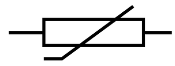
Thermistors are used as temperature sensors. The symbol for a thermistor is shown below.
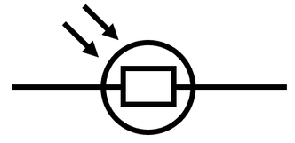
LDRs are light-dependent resistors. The symbol for an LDR is shown below.
We are now going to have a look at two sensing circuits; one circuit with a thermistor in and another circuit with an LDR in. Sensing circuits are used to turn on or increase the power to certain components in a circuit depending on the conditions that the circuit is operating in.
The circuits that we are going to look at involve the rules to do with series and parallel circuits. Therefore, it is worth going through the series and parallel circuit content before looking at the circuits below. Click here for the content about series circuits and click here for the content about parallel circuits.
The circuit below is used to control an automatic fan in a room.
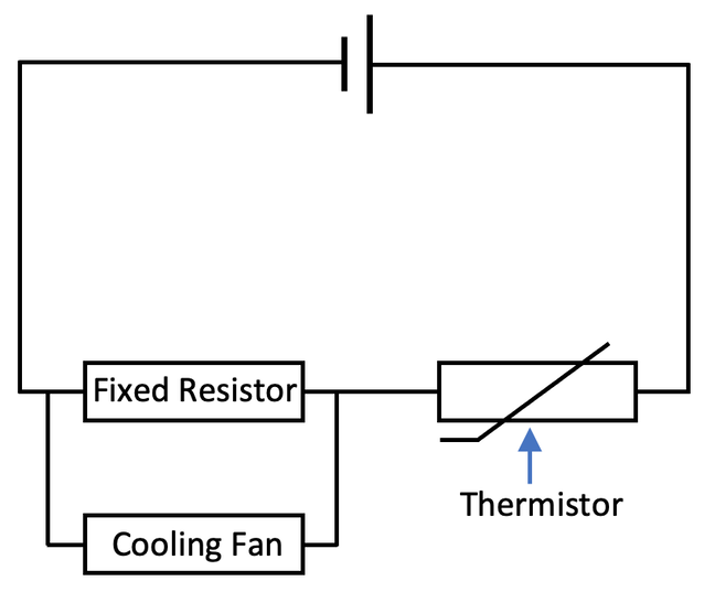
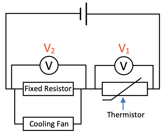
The thermistor and the “loop” are connected in series with each other. This means that the source potential difference (PD from the power supply) will be shared out between the thermistor and the “loop”; Vtotal = V1 + V2. With series circuits, the potential difference is shared out based on the component’s resistance; components with a greater resistance receive a greater proportion of the source potential difference.
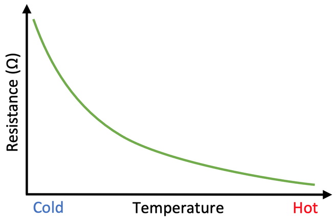
In cold conditions, the resistance of the thermistor is high, which means that the thermistor takes a greater proportion of the source potential difference, thus meaning that the potential difference of the loop is very low; V1 is high and V2 is low. A low potential difference in the loop/ across the fan means that the fan will be off/ moving very slowly.
In hotter conditions, the resistance of the thermistor is low, which means that the thermistor takes a small proportion of the source potential difference, thus meaning that the potential difference of the loop is quite high; V1 is low and V2 is high. A higher potential difference in the loop/ across the fan means that the fan will turn on/ move faster.
The circuit below is used to control an automatic light (such as an automatic light in your garden).
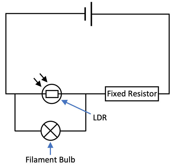
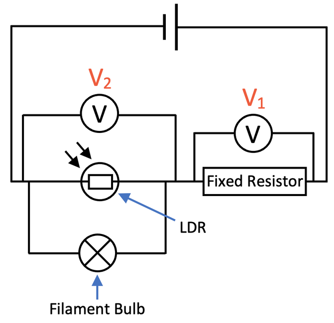
The fixed resistor and the “loop” are connected in series with each other. This means that the source potential difference (PD from the power supply) will be shared out between the fixed resistor and the “loop”; Vtotal = V1 + V2. With series circuits, the potential difference is shared out based on the component’s resistance; components with a greater resistance receive a greater proportion of the source potential difference.
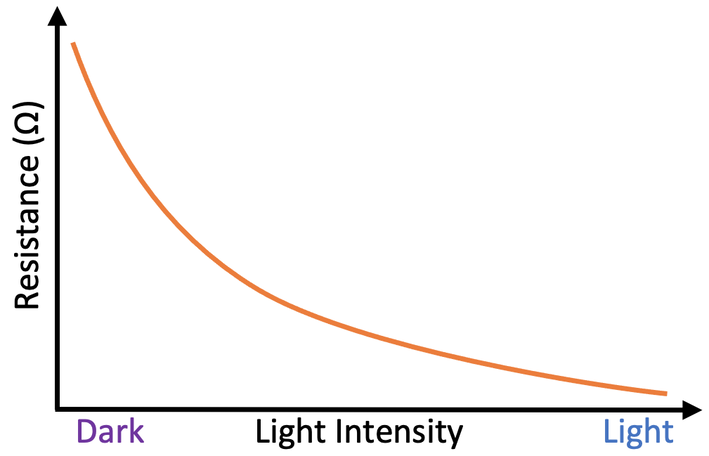
When it is dark, the resistance of the LDR is very high, which means that the loop takes a greater proportion of the source potential difference compared with the fixed resistor; V1 is low and V2 is high. A greater potential difference across the loop means a greater potential difference across the bulb. The brightness of a bulb is determined by power and we work out power by multiplying current by potential difference (P = IV). A greater potential difference across the bulb means that there is a greater power, thus resulting in the bulb getting brighter/ turning on. So, in dark conditions, the bulb turns on/ shines more brightly.
When it is light, the resistance of the LDR is very low, which means that the loop takes a smaller proportion of the source potential difference compared with the fixed resistor; V1 is high and V2 is low. A smaller potential difference across the loop and bulb means that the power of the bulb is low (P = IV). A smaller power means that the brightness of the bulb decreases/ the bulb turns off. So, in light conditions, the bulb turns off/ shines less brightly.
The two circuits that we have just looked at are quite complex. Therefore, you will probably need to go over these circuits and the rules for series and parallel circuits a few times before you feel fully comfortable with these circuits.