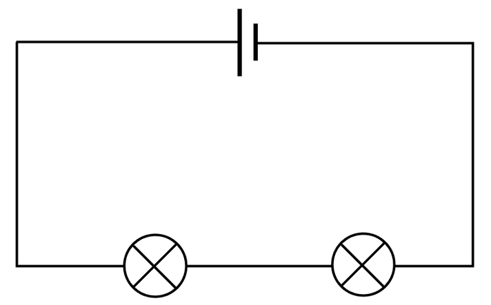
In a series circuit, all of the components are connected in a line between the positive and the negative of the power supply (cell or battery). If one of the components is removed or disconnected, the circuit is broken and all of the other components will stop working. This is why series circuits are rarely used. The circuit below is a series circuit with 2 filament bulbs.
We are now going to have a look at a few rules to do with the current, potential difference and resistance for series circuits. Before we look at these rules, we need to place some ammeters and voltmeters on the above circuit. Ammeters measure the current and need to be placed in series; I am going to place 2 ammeters in the circuit. Voltmeters measure the potential difference and need to be placed in parallel around the component that they are finding the potential difference of; we place a voltmeter around each of the filament bulbs. The circuit containing two ammeters and two voltmeters is shown below.
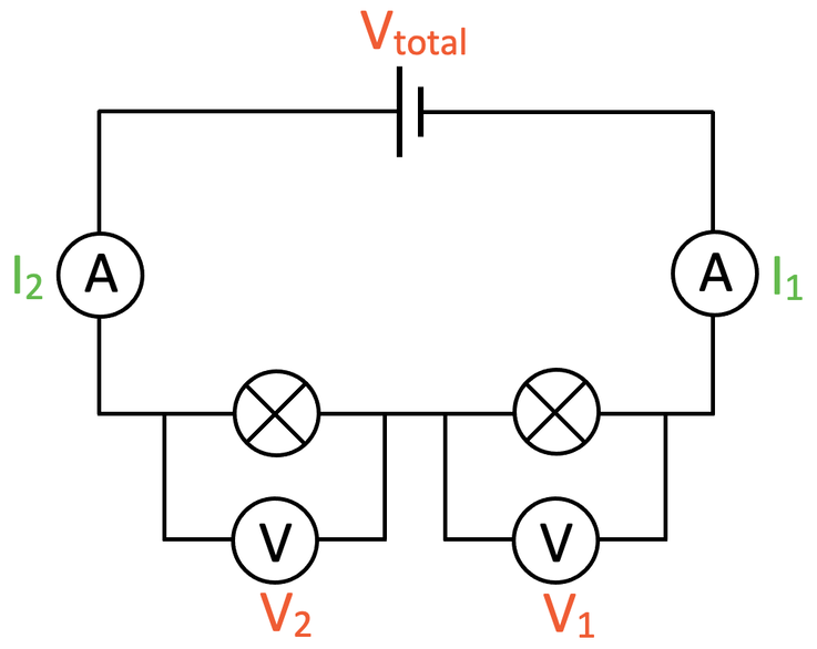
Voltmeters and ammeters do not count as part of the circuit, so this circuit is still a series circuit despite the two voltmeters being in parallel.
Let’s now have a look at the rules.
Let’s now have a look at the rules.
Potential Difference is Shared
The total potential difference is shared between the different components in the series circuit; the source potential difference (the potential difference from the cell or battery) will be equal to the sum of the potential differences from all of the different components. This gives us the equation:
The total potential difference is shared between the different components in the series circuit; the source potential difference (the potential difference from the cell or battery) will be equal to the sum of the potential differences from all of the different components. This gives us the equation:

For our filament bulb circuit, we would just have V1 + V2 as there were only two components.
The potential difference from the cell or battery does not have to be shared equally between all of the components in the series circuit; for the rule, V1 may not be the same as V2, which may not be the same as V3 etc…. However, if the filament bulbs were identical in the above circuit, the potential difference across each of the filament bulbs would be the same. We will be looking at some mathematical examples after we have covered the other rules.
Current is the Same Everywhere
In a series circuit, the current is the same everywhere in the circuit. Therefore, for our circuit with the two filament bulbs, the reading for the current on ammeter 1 and ammeter 2 will be the same. This gives us the rule below.
In a series circuit, the current is the same everywhere in the circuit. Therefore, for our circuit with the two filament bulbs, the reading for the current on ammeter 1 and ammeter 2 will be the same. This gives us the rule below.

We can work out the current in a series circuit by dividing the total potential difference (source PD from the cell or battery) by the total resistance (the resistance of all of the components added together). The equation is shown below.

Resistance Adds Up
In a series circuit, the total resistance in a circuit is the sum of the resistances of the individual components. The equation for this is shown below.
In a series circuit, the total resistance in a circuit is the sum of the resistances of the individual components. The equation for this is shown below.

Some Examples
We are now going to have a look at some mathematical examples that require us to remember the 3 rules, which are:
Click here for a printable PDF of the circuits in the examples.
Example 1
The circuit below has a battery connected to two resistors in series. The potential difference of the battery is 20 V.
We are now going to have a look at some mathematical examples that require us to remember the 3 rules, which are:
- Potential difference is shared (not necessarily equally)
- Current is the same everywhere
- Resistance adds up
Click here for a printable PDF of the circuits in the examples.
Example 1
The circuit below has a battery connected to two resistors in series. The potential difference of the battery is 20 V.
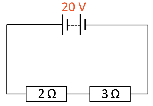
Find the following:
a) The current for the circuit
b) The potential difference across the 2 Ω resistor
c) The potential difference across the 3 Ω resistor
Part a
The circuit above is a series circuit. We know that in series circuits, the current is the same everywhere in the circuit. We work out the current in the circuit by dividing the total potential difference by the total resistance.

The total potential difference for this circuit is the potential difference of the battery, which is 20 V. We find the total resistance by adding up the resistances of all of the components in the circuit; we add the resistances of the two resistors together which is 5 Ω (2 Ω + 3 Ω). We now put the total potential difference as 20 V and the total resistance as 5 Ω into the calculation for the current.

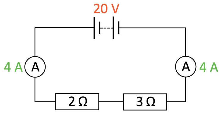
The current everywhere in the circuit is 4 A.
If we placed two ammeters anywhere in the circuit in series, both of the ammeters would read 4 A. The circuit with two ammeters in is shown below.
If we placed two ammeters anywhere in the circuit in series, both of the ammeters would read 4 A. The circuit with two ammeters in is shown below.
Part b
Part b asks us to work out the potential difference across the 2 Ω resistor. We work out the potential difference by multiplying the current by the resistance.
Part b asks us to work out the potential difference across the 2 Ω resistor. We work out the potential difference by multiplying the current by the resistance.

From part a, we know that the current for the whole circuit is 4 A and we know that the resistance of this resistor is 2 Ω.
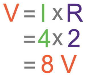
The potential difference across the 2 Ω resistor is 8 V.
Part c
Part c asks us to work out the potential difference across the 3 Ω resistor. Like part b, we work out the potential difference by multiplying the current by the resistance.
Part c
Part c asks us to work out the potential difference across the 3 Ω resistor. Like part b, we work out the potential difference by multiplying the current by the resistance.

From part a, we know that the current for the whole circuit is 4 A and we know that the resistance of this resistor is 3 Ω.
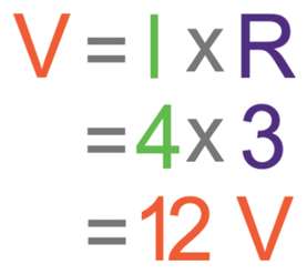
The potential difference across the 3 Ω resistor is 12 V.
Checking the Rule
For series circuits, the rule is that source potential difference is shared. The rule is:
Checking the Rule
For series circuits, the rule is that source potential difference is shared. The rule is:

I am now going to add two voltmeters in parallel around each of the resistors.
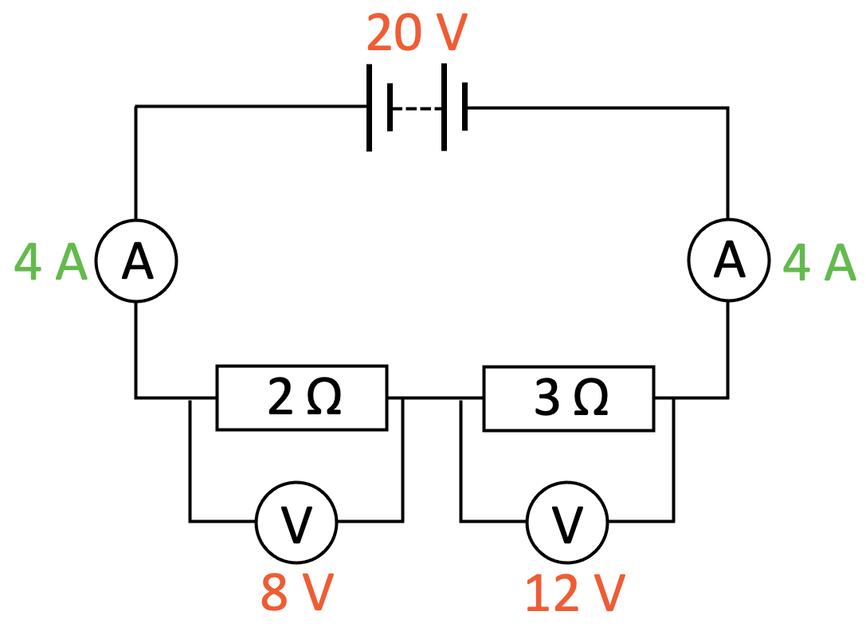
The source potential difference is the potential difference of the battery, which is 20 V. This should be equal to the sum of the potential differences across the two resistors; the PD of the 2 Ω resistor is 8 V and the PD of the 3 Ω resistor is 12 V.
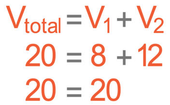
From the above calculation, we can see that this is true. Also, we can see that the source potential difference is shared, but it is not shared equally. A component with a greater resistance will take a greater proportion of the source potential difference. For this circuit, the 3 Ω resistor had a greater resistance and it had a potential difference of 12 V (the 2 Ω resistor had a lower resistance and a lower potential different [8 V]).
Example 2
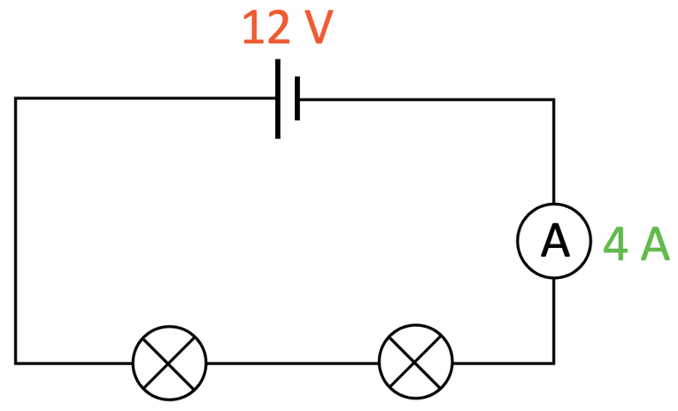
The circuit below has two identical filament bulbs connected in series.
The circuit below has two identical filament bulbs connected in series.

The cell has a potential difference of 12 V and the reading on the ammeter is 4 A. Work out the resistance of each of the filament bulbs.
There are two different ways that we can work out the resistance of each of the filament bulbs.
Way 1
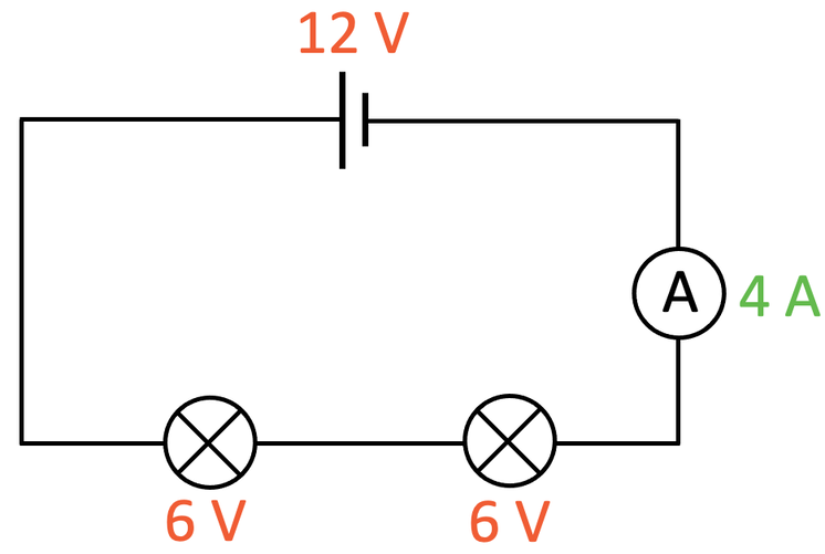
The above circuit is a series circuit, which means that the source potential difference (12 V) will be shared between the different components in the circuit; the 12 V will be shared between the two filament bulbs. The question tells us that the filament bulbs are identical to each other. This means that the source potential difference (12 V) will be shared equally with each of the filament bulbs. Therefore, the potential difference across each of the filament bulbs is 6 V (12 V ÷ 2). I am going to add 6 V under each of the filament bulbs in the circuit.
There are two different ways that we can work out the resistance of each of the filament bulbs.
Way 1
The above circuit is a series circuit, which means that the source potential difference (12 V) will be shared between the different components in the circuit; the 12 V will be shared between the two filament bulbs. The question tells us that the filament bulbs are identical to each other. This means that the source potential difference (12 V) will be shared equally with each of the filament bulbs. Therefore, the potential difference across each of the filament bulbs is 6 V (12 V ÷ 2). I am going to add 6 V under each of the filament bulbs in the circuit.
The current in series circuits is the same throughout the whole circuit; therefore, the current through the whole circuit and each of the filament bulbs is 4 A (the question told us the current). We can now work out the resistance of one of the filament bulbs by dividing the potential difference across the bulb (6 V) by the current through the bulb (4 A).

The resistance of each of the bulbs is 1.5 Ω.
Way 2
The second way involves working out the total resistance of the circuit and then dividing the total resistance by the number of filament bulbs. Here is the circuit again before we did any working.
Way 2
The second way involves working out the total resistance of the circuit and then dividing the total resistance by the number of filament bulbs. Here is the circuit again before we did any working.
We can find the total resistance of the circuit by dividing the total potential difference by the current.

The total potential difference of the circuit is the potential difference from the cell, which is 12 V. The current in the circuit is 4 A.

The two filament bulbs in the circuit are identical to each other, which means that they will have the same resistance. Therefore, we can work out the resistance of each of the filament bulbs by dividing the total resistance in the circuit (3 Ω) by the number of bulbs (2).

Therefore, the resistance of each of the filament bulbs is 1.5 Ω.
Example 3
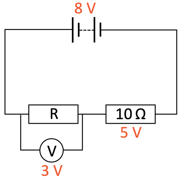
The circuit below has a cell with a potential difference of 8 V. There are two resistors in the circuit; one of the resistors has a resistance of 10 Ω and the other resistor has an unknown resistance (labelled R). The potential difference across resistor R is 3 V.
The circuit below has a cell with a potential difference of 8 V. There are two resistors in the circuit; one of the resistors has a resistance of 10 Ω and the other resistor has an unknown resistance (labelled R). The potential difference across resistor R is 3 V.
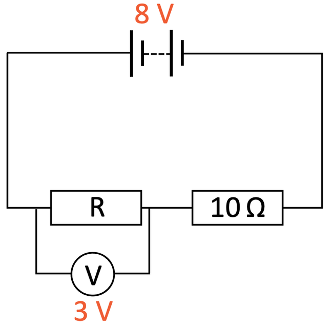
Find the resistance of the unknown resistor.
This is a series circuit, and we know that in series circuits the source potential difference is equal to the sum of the potential differences of the different components. The source potential difference is 8 V, which will be equal to the sum of the potential differences across the 10 Ω resistor and the unknown resistor (3 V). From this information, we can create the following equation to work out the potential difference across the 10 Ω resistor.
This is a series circuit, and we know that in series circuits the source potential difference is equal to the sum of the potential differences of the different components. The source potential difference is 8 V, which will be equal to the sum of the potential differences across the 10 Ω resistor and the unknown resistor (3 V). From this information, we can create the following equation to work out the potential difference across the 10 Ω resistor.
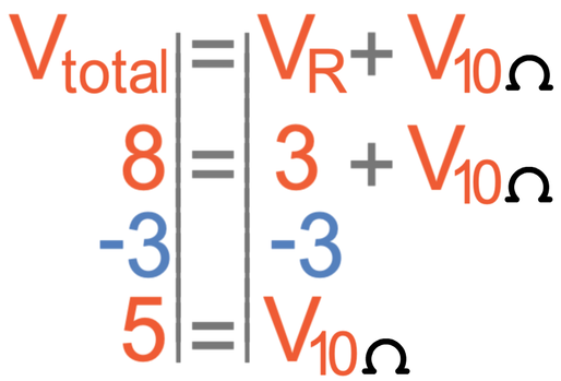
The potential difference across the 10 Ω resistor is 5 V.
The next step is to work out the current passing through the 10 Ω resistor. We can work out the current by dividing the potential difference by the resistance. The potential difference of the 10 Ω resistor is 5 V and the resistance is 10 Ω

The current passing through the 10 Ω resistor is 0.5 A.
For series circuits, the current is the same throughout the whole circuit. This means that the current through resistor R will also be 0.5 A. We are now in a position to work out the resistance of resistor R by dividing the potential difference across resistor R (3 V) by the current (0.5 A).
For series circuits, the current is the same throughout the whole circuit. This means that the current through resistor R will also be 0.5 A. We are now in a position to work out the resistance of resistor R by dividing the potential difference across resistor R (3 V) by the current (0.5 A).

The resistance of resistor R is 6 Ω.