We learnt about the rules for total resistance in a circuit for series and parallel circuits in the previous sections. We are now going to have a look at an investigation that will prove that these rules that we learnt to do with total resistance are true. We will be using identical resistors in this experiment. Let’s start by investigating how total resistance changes when we add more resistors in a series circuit.
Series Circuits
A series circuit is where all of the different components are connected in a line between the positive and the negative of the power supply (cell or battery). We can investigate the effect that the number of identical resistors has on the total resistance in a series circuit by building the circuit below.
A series circuit is where all of the different components are connected in a line between the positive and the negative of the power supply (cell or battery). We can investigate the effect that the number of identical resistors has on the total resistance in a series circuit by building the circuit below.
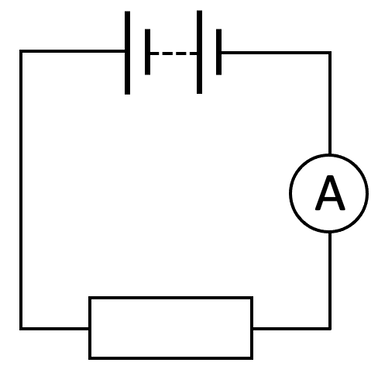
We find the total resistance of the circuit by dividing the source potential difference (the PD of the cell or battery) by the current (measured by the ammeter).
We then add another identical resistor to the circuit in series to make the circuit look like what is shown below.
We then add another identical resistor to the circuit in series to make the circuit look like what is shown below.
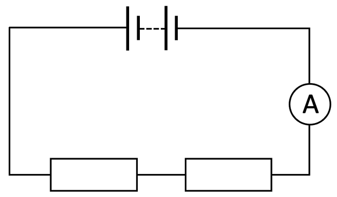
We then work out the total resistance of the circuit with 2 resistors by dividing the source potential difference (which will be the same as the circuit with 1 resistor) by the current reading on the ammeter (which will be less than the circuit with 1 resistor).
We continue the process of adding more identical resistors in series to the circuit and working out the total resistance of the circuit until we have readings for around 6 to 8 resistors in the circuit. The next step is to plot our results on a graph with the number of identical resistors on the x-axis and the total resistance of the circuit on the y-axis. The graph will look something like what is shown below.
We continue the process of adding more identical resistors in series to the circuit and working out the total resistance of the circuit until we have readings for around 6 to 8 resistors in the circuit. The next step is to plot our results on a graph with the number of identical resistors on the x-axis and the total resistance of the circuit on the y-axis. The graph will look something like what is shown below.
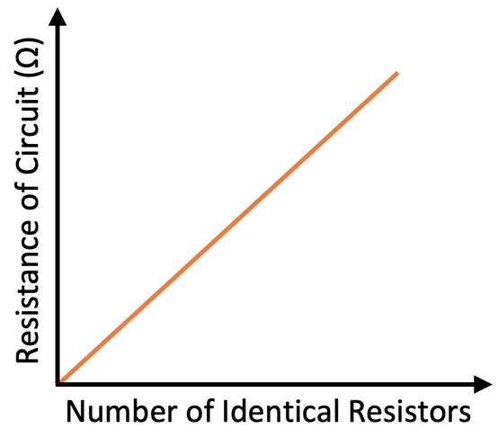
From the above graph, we can see that as we add more identical resistors in series, the total resistance of the circuit increases. This proves the resistance rule for series circuits, which is that the total resistance in a series circuit is the sum of the resistances of all of the components in the series circuit.
Also, it is worth mentioning that as the number of identical resistors in the series circuit increases, the current of the circuit decreases; we find the current in a series circuit by dividing the source potential difference by the total resistance.
Also, it is worth mentioning that as the number of identical resistors in the series circuit increases, the current of the circuit decreases; we find the current in a series circuit by dividing the source potential difference by the total resistance.
Parallel Circuits
In parallel circuits, each component is seperately connected to the positive and negative of the power supply (cell or battery). We can investigate the effect that the number of identical resistors has on the total resistance in a parallel circuit by building the circuit below.
In parallel circuits, each component is seperately connected to the positive and negative of the power supply (cell or battery). We can investigate the effect that the number of identical resistors has on the total resistance in a parallel circuit by building the circuit below.

Like the previous investigation with the series circuit, we work out the total resistance of the circuit by dividing the source potential difference by the reading for the current on the ammeter.
We then add another identical resistor to the circuit in parallel to the existing resistor. The circuit will look like what is shown below.
We then add another identical resistor to the circuit in parallel to the existing resistor. The circuit will look like what is shown below.
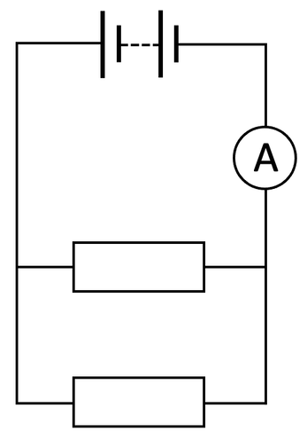
We work out the total resistance of the circuit with 2 resistors by dividing the source potential difference (which will be the same as the circuit with 1 resistor) by the current reading on the ammeter (which will be more than the circuit with 1 resistor).
We continue the process of adding more identical resistors to the circuit in parallel to the existing resistors and working out the total resistance of the circuit until we have readings for around 6 to 8 resistors in the circuit. The next step is to plot our results on a graph with the number of identical resistors on the x-axis and the total resistance of the circuit on the y-axis. The graph will look something like what is shown below.
We continue the process of adding more identical resistors to the circuit in parallel to the existing resistors and working out the total resistance of the circuit until we have readings for around 6 to 8 resistors in the circuit. The next step is to plot our results on a graph with the number of identical resistors on the x-axis and the total resistance of the circuit on the y-axis. The graph will look something like what is shown below.
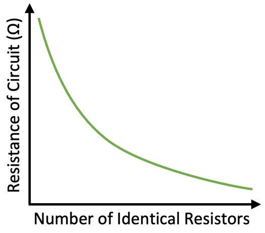
From the above graph, we can see that as we add more identical resistors in parallel, the total resistance of the circuit decreases. This is because the adding of additional branches/ loops means that the current has more pathways to go down, which means that more total current can travel around the circuit; the total current increases. Resistance is worked out by dividing source potential difference by total current (R = V ÷ I). When there are more branches in parallel circuits, the total current increases (I) and the source potential difference stays the same (V), which means that the total resistance decreases (R).
Summary
Here is a summary of what happens in series and parallel circuits when we add identical resistors to the circuits:
Here is a summary of what happens in series and parallel circuits when we add identical resistors to the circuits:
- In series circuits, the adding of more identical resistors in series increases the total resistance of the circuit, which decreases the current in the circuit. The line on the graph is straight.
- In parallel circuits, the adding of more identical resistors in parallel decreases the total resistance of the circuit and increases the total current in the circuit. The line on the graph is curved.
Modification of the Circuits
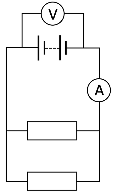
I knew the source potential difference in both of the experiments (the PD of the cell or battery). If we did not know the source potential difference, we could find it by adding a voltmeter in parallel around the power source (cell or battery). The location of the voltmeter will be the same for both the series circuits and parallel circuits. A voltmeter is shown below on a parallel circuit with 2 identical resistors.
I knew the source potential difference in both of the experiments (the PD of the cell or battery). If we did not know the source potential difference, we could find it by adding a voltmeter in parallel around the power source (cell or battery). The location of the voltmeter will be the same for both the series circuits and parallel circuits. A voltmeter is shown below on a parallel circuit with 2 identical resistors.