Back to P7 Home
P7 E) I-V Graphs
P7 E) I-V Graphs
Resistance of Difference Components
When the current passing through a component changes, sometimes the resistance of the component also changes and other times the resistance of the component stays the same. We are going to see what happens to an ohmic conductor, a filament bulb and a diode when the current passing through them changes.
Ohmic Conductors
Wires and resistors are examples of ohmic conductors. At a constant temperature, the resistance of an ohmic conductor is constant. This means that the current through the ohmic conductor and the potential difference across the ohmic conductor are in direct proportion to each other (V = IR); when the current passing through the ohmic conductor increases, so too does the potential difference across the ohmic conductor.
Filament Bulbs
A filament bulb contains a thin coil of wire, which is known as the filament. When an electrical current passes through a filament bulb, the filament heats up and produces light. The resistance of the filament bulb increases as the temperature of the filament increases. A greater current results in the temperature of the filament increasing, which increases the resistance of the filament bulb.
Diodes
Diodes only allow a current to flow through them in one direction. If the current is flowing in the correct direction, the diode will let the current through. However, if the current is flowing in the wrong direction, the resistance of the diode will be extremely high and the diode will not let the current flow through.
I-V Graphs
We can complete an experiment to investigate how the potential difference changes as current changes for an ohmic conductor, a filament bulb and a diode. We can then draw a current-potential difference graph (I-V graph). The circuit for the experiment contains a battery, variable resistor, ammeter, voltmeter and the component that we are testing (ohmic conductor, filament bulb or diode). The ammeter is placed in series and the voltmeter is placed in parallel around the component that we are testing. The circuit is shown below.
We can complete an experiment to investigate how the potential difference changes as current changes for an ohmic conductor, a filament bulb and a diode. We can then draw a current-potential difference graph (I-V graph). The circuit for the experiment contains a battery, variable resistor, ammeter, voltmeter and the component that we are testing (ohmic conductor, filament bulb or diode). The ammeter is placed in series and the voltmeter is placed in parallel around the component that we are testing. The circuit is shown below.
We complete the experiment by altering the resistance of the variable resistor. This alters the current travelling around the whole circuit, which in turn varies the potential difference across the component that we are testing; when we increase the resistance of the variable resistor, the current will decrease (and vice versa). After varying the resistance of the variable resistor, we then take readings for the current from the ammeter and potential difference from the voltmeter. We vary the resistance quite a few times and take readings for current and potential difference. We should repeat our experiment and find the average potential difference for each current.
We then swap over the wires connecting the power source (cell or battery) so that the current travels around the circuit in the opposite direction. We do the same process; vary the resistance of the variable resistor and take readings for current and potential difference.
When we have quite a few values for current and average potential difference, we can plot them on an I-V graph. The I-V graphs have potential difference (V) on the x-axis and current (I) on the y-axis. The graphs for the 3 components are shown below.
Ohmic Conductor at a Constant Temperature
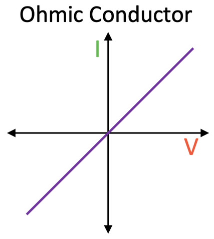
A wire and a resistor are examples of ohmic conductors.
A wire and a resistor are examples of ohmic conductors.
The current through an ohmic conductor (at a constant temperature) is directly proportional to the potential difference across the ohmic conductor. This is because the resistance of the ohmic conductor (at a constant temperature) remains constant. The line on an I-V graph for an ohmic conductor will always be straight and pass through the origin.
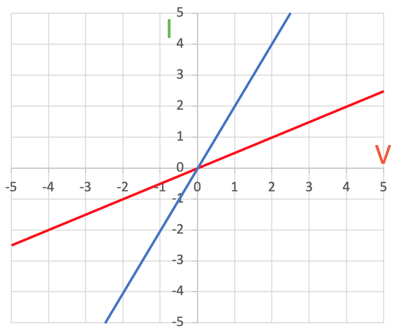
The gradient of the line (steepness) depends on the resistance of the ohmic conductor. Let’s suppose that the ohmic conductor is a resistor. A steeper line on the I-V graph indicates that the resistor has a lower resistance. And, a flatter line on the I-V graph indicates that the resistor has a higher resistance. If we look at the graph below, we can see that the resistor that is plotted with the red line has a higher resistance compared to the resistor that is plotted with the blue line (the blue line is steeper than the red line, thus meaning that the blue resistor has a lower resistance).
The gradient of the line (steepness) depends on the resistance of the ohmic conductor. Let’s suppose that the ohmic conductor is a resistor. A steeper line on the I-V graph indicates that the resistor has a lower resistance. And, a flatter line on the I-V graph indicates that the resistor has a higher resistance. If we look at the graph below, we can see that the resistor that is plotted with the red line has a higher resistance compared to the resistor that is plotted with the blue line (the blue line is steeper than the red line, thus meaning that the blue resistor has a lower resistance).
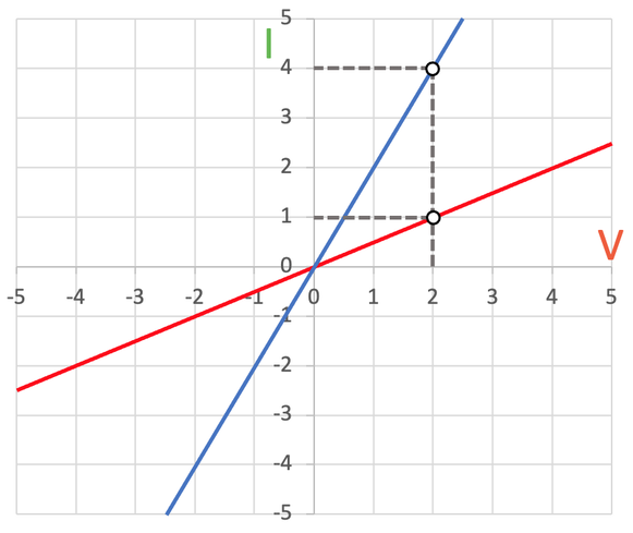
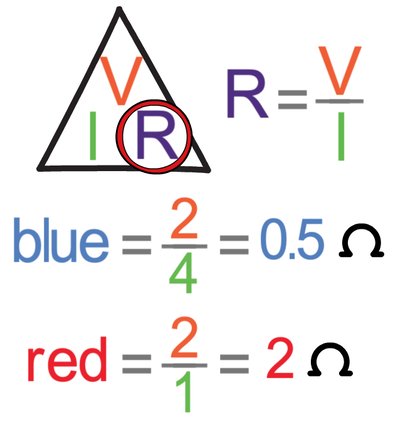
We can show that the resistance is greater for the red resistor than the blue resistor by choosing a point on each of the lines to work out the resistance; we work out the resistance by dividing the potential difference (V) by the current (I). My working for the resistance of both of the resistors is shown below.
The resistance of the red resistor is 2 Ω and the resistance of the blue resistor is 0.5 Ω. So, the steeper the line, the lower the resistance. And, the flatter the line, the greater the resistance.
Filament Bulbs
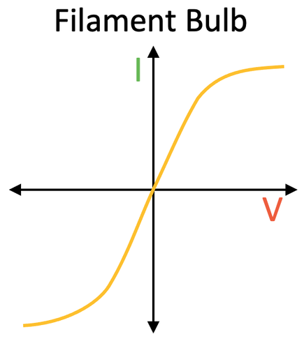
The I-V graph for a filament bulb is shown below.
The I-V graph for a filament bulb is shown below.
A filament bulb contains a thin coil of wire, which is known as the filament. When an electrical current passes through a filament bulb, the filament heats up and produces light. The resistance of the filament bulb increases as the temperature of the filament increases. A greater current results in the temperature of the filament increasing, which increases the resistance of the filament bulb. This means that less current can flow through the filament bulb per unit of potential difference. This is why the I-V graph starts to curve when the current increases.
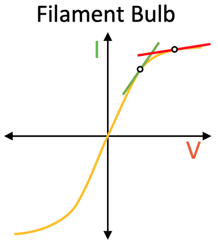
To show that the resistance of a filament bulb does increase when the current increases, I will draw two tangents on the curve.
To show that the resistance of a filament bulb does increase when the current increases, I will draw two tangents on the curve.
From the I-V graphs for the ohmic conductors, we learnt that a steeper line means a lower resistance and a flatter line means a greater resistance. From the two tangents on the graph above, we can see that the tangent with a lower current (green) is steeper than the tangent with a higher current (red). This means that at low currents the resistance of the filament bulb is low (green line), and at higher currents the resistance of the filament bulb is high (red line). This happens because a greater current causes the temperature of the filament bulb to increase, which increases the resistance of the filament bulb.
Diodes
The final I-V graph that you need to know is the one for a diode.
The final I-V graph that you need to know is the one for a diode.
Diodes only allow a current to flow through them in one direction. If the current is flowing in the correct direction, the diode will let the current through. However, if the current is flowing in the wrong direction, the resistance of the diode will be extremely high, thus meaning that no current will be able to pass through the diode; the curve for the current flowing in the wrong direction will be along the x-axis.
The Three Graphs
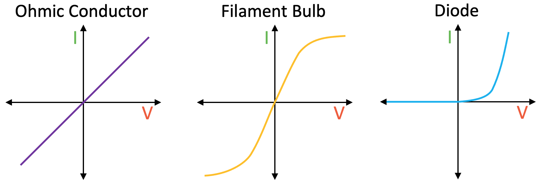
Here are all three of the I-V graphs together. It is worth getting them down on a revision card with a few notes explaining why the graphs have the shapes that they have.
Here are all three of the I-V graphs together. It is worth getting them down on a revision card with a few notes explaining why the graphs have the shapes that they have.


