Back to P7 Home
P7 B) Circuit Symbols
P7 B) Circuit Symbols
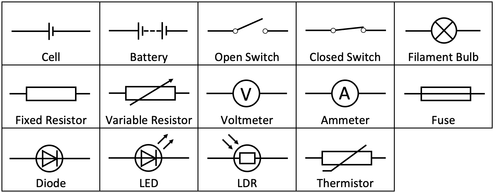
Here are the circuit symbols for the components that you are required to know for the exam.
Here is some more information about the components.
We are now going to have a look at an example of drawing a basic circuit. When we are drawing circuits, we use straight lines to connect the different components; the straight line represent wiring. We also need to make sure that the circuit that we draw is closed (there are no gaps).
- Cell – a cell is a single unit device that converts chemical energy into electrical energy. A cell is a source of potential difference that pushes the electrical charge around a circuit.
- Battery – a battery is a set of connected cells, hence why the symbol for a battery is two or more cells next to each other. A battery is also a source of potential difference that pushes the electrical charge around a circuit.
- Switch open – a switch can complete or break a circuit. When a switch is open, the circuit is broken, which means that an electrical charge will not flow around the circuit. You can see from the open switch symbol that the black line (the wire) is not connected/ there is a gap in the black line.
- Switch closed – a closed switch completes the circuit and therefore means that an electrical charge can flow around the circuit. You can see this from the closed switch symbol because the black line is connected.
- Filament bulb or filament lamp – a filament bulb/ lamp turns electrical energy into light energy (useful energy) and heat.
- Fuse – a fuse is a component that is designed to break if there is an excessive current (a current that is too high). Fuses break to protect the wiring of appliances.
- Voltmeter – a voltmeter measures the potential difference.
- Ammeter – an ammeter measures the current.
- Diode – diodes only allow a current to flow through them in one direction; they have a very high resistance in the other direction. The direction of the arrowhead on diode symbol tells us the direction that the current can pass through a diode. For the diode in the table at the top, the current can pass through the diode from left to right, and the current cannot pass through the diode from right to left.
- Fixed resistor – a resistor reduces the flow of electrical charge/ current.
- Variable resistor – we can change the resistance of a variable resistor. Like a fixed resistor, a variable resistor will reduce the flow of electrical charge/ current.
- Thermistor – the resistance of a thermistor varies with temperature (we will be looking at thermistors in a lot more detail in a later section).
- LDR – light-dependent resistors. The resistance of an LDR varies with light (we will be looking at LDRs in a lot more detail in a later section).
- LED – light-emitting diode. An LED is a special type of diode that emits light when a current passes through it. Like a diode, a current can only pass through an LED in one direction (the direction of the arrowhead).
We are now going to have a look at an example of drawing a basic circuit. When we are drawing circuits, we use straight lines to connect the different components; the straight line represent wiring. We also need to make sure that the circuit that we draw is closed (there are no gaps).
Example 1
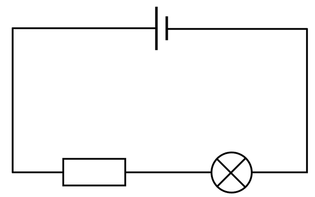
I create a circuit using a cell, a resistor and a filament bulb. I connect all of the components in a single closed loop (in series). Draw a diagram for this circuit.
The question tells us that all of the components are connected in a single closed loop (in series). Therefore, we draw the three components and then connect them with straight continuous wire lines. The circuit is shown below.


