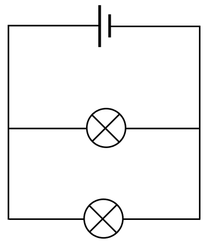
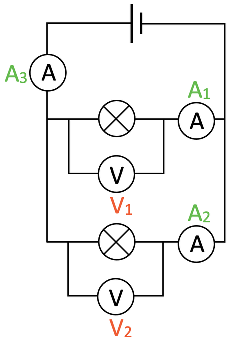
All of the components in a parallel circuit receive the full source potential difference (the potential difference from the cell or battery). This means that both of the filament bulbs get the same potential difference that the cell produces; if the potential difference of the cell was 6 V, the reading on voltmeter 1 would be 6 V and the reading on voltmeter 2 would also be 6 V. This gives us the rule:
In parallel circuits, the total current through the whole circuit is the sum of the currents through the separate branches. The rule is:
Also, parallel circuits have junctions where the circuit splits from 1 into 2, or rejoins from 2 to become 1. At junctions, the current going into a junction will be equal to the current coming out of a junction.
If a circuit contained two identical components connected in parallel, the same current will pass through both of the branches/ components. My circuit contains two identical filament bulbs, which means that the current on ammeter 1 and ammeter 2 will be the same (A1 = A2). However, if the components are different, the current passing through each of the branches/ components will not be the same.
The rule for total resistance in parallel circuits is that the adding of more resistors to the circuit in parallel decreases the total resistance in the circuit. This is quite hard to understand, so we will have a look at a mathematical example later to prove that this is the case.
We are now going to have a look at some mathematical examples that require us to remember the 3 rules, which are:
- Potential difference is the same across all components
- Current is shared between branches
- Adding more resistors decreases the total resistance in the circuit
Click here for a printable PDF of the circuits in the examples.
Example 1
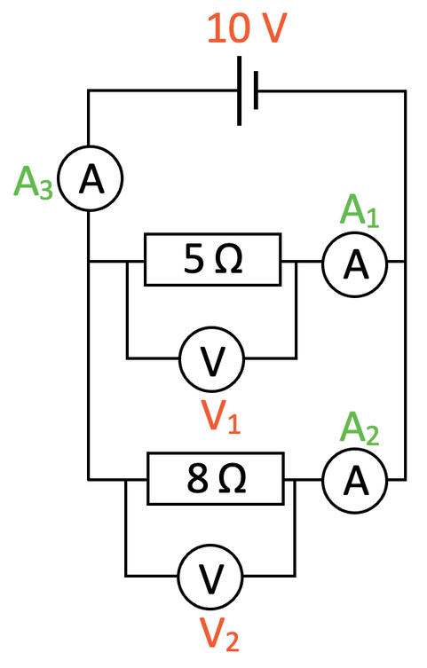
We have the circuit below.
Find the following:
a) The potential difference values on V1 and V2
b) The current values on A1 and A2
c) The current value on A3
Part a
This part asks us to work out the values for the potential difference on voltmeter 1 and 2. This is a parallel circuit and we know that the potential difference is the same across all components in a parallel circuit; all of the components in a parallel circuit receive the full source potential difference from the battery or cell. The diagram of the circuit tells us that the source potential difference from the cell is 10 V. Therefore, the reading on both V1 and V2 will be 10 V as all of the components in the parallel circuit receive this full potential difference.
Part b
This part asks us to find the values for the current on A1 and A2. We work out the current for A1 and A2 separately.
I am going to work out the current for A1 first. The reading on A1 will be the current through the 5 Ω resistor (as there is only 1 component on this branch). We find the current through a component by dividing the potential difference across the component by the resistance of the component. The potential difference across the 5 Ω resistor is 10 V (found in part a) and the resistance of this resistor is 5 Ω. The calculation is:
The current passing through the 5 Ω resistor is 2 A. Therefore, the reading on A1 will be 2 A.
We now need to work out the current for A2. The reading on A2 will be the current through the 8 Ω resistor (as there is only 1 component on this branch). Like we did for A1, we find the current through the 8 Ω resistor by dividing the potential difference across the component by the resistance of the component. The potential difference across the 8 Ω resistor is 10 V (found in part a) and the resistance of this resistor is 8 Ω.
The current passing through the 8 Ω resistor is 1.25 A. Therefore, the reading on A2 will be 1.25 A.
So, the current for A1 is 2 A and the current for A2 is 1.25 A. Also, you can see that the currents for each of the branches are not equal.
Part c
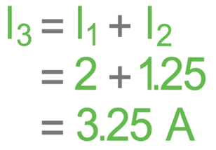
The final part of this question asks us to find the value for current on A3. For parallel circuits, the total current going into a junction (splitting or rejoining) will be equal to the total current leaving the junction. This means that the value for the current on A3 will be equal to the sum of the currents on the two branches (the values for A1 and A2).
The value for the current for A3 is 3.25 A.
Resistance Rule
I am now going to use this circuit to demonstrate the resistance rule, which is that the adding of more resistors to a circuit in parallel decreases the total resistance in the circuit. We have worked out that the total current going around the above circuit is 3.25 A (the reading on A3). The potential difference of the circuit is the source potential difference, which is 10 V. We find the total resistance of the circuit by dividing the source potential difference (10 V) by the current (3.25 A).
The total resistance of the circuit is 3.1 Ω (to 1 dp). This is less than the resistance of the smaller resistor (which was 5 Ω).
Why is this the case? The potential difference in parallel circuits is the same everywhere. The adding in of additional branches/ loops means that the current has more pathways to go down, which allows more total current to travel around the circuit; the total current increases. Resistance is worked out by dividing potential difference by total current (R = V ÷ I). When there are more branches in parallel to each other, the total current will increase, which means that the total resistance decreases.
Example 2
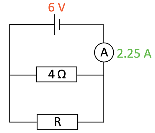
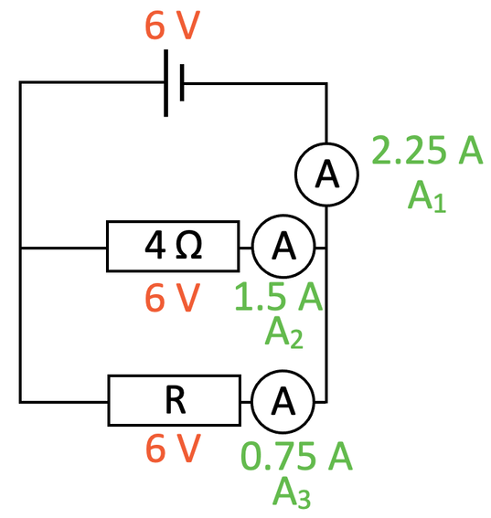
We have the circuit below.
The reading on the ammeter (which I will call A1) is 2.25 A. Find the resistance for the resistor labelled R.
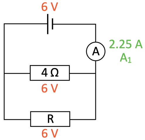
This is a parallel circuit and one of the rules for parallel circuits is that the potential difference across all of the components is the same as the source potential difference. Therefore, the potential difference across both resistors is 6 V. I have added these values to the diagram.
We can now find the current that passing through the 4 Ω resistor because we have the potential difference (6 V) and the resistance (4 Ω). We find the current by dividing the potential difference (6 V) by the resistance (4 Ω).
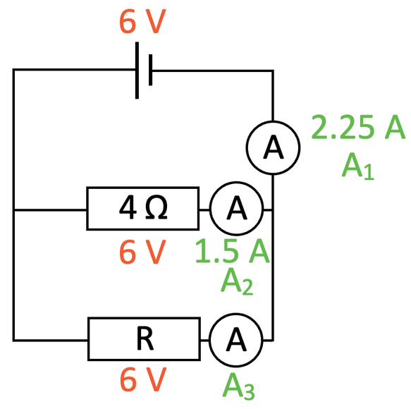
The current through the 4 Ω resistor is 1.5 A. I am going to add an ammeter for this branch reading 1.5 A (A2) and an ammeter for the next branch (A3) to the circuit diagram.
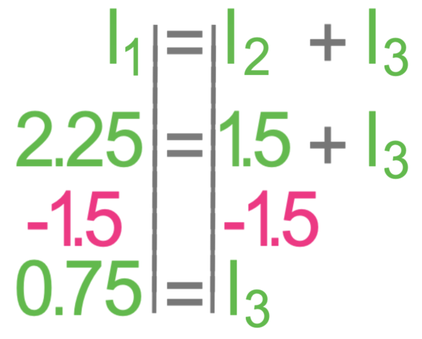
In parallel circuits, we know that the total current going into a junction (splitting or rejoining) will be equal to the total current leaving the junction. This means that the reading for the ammeter that we are given (A1: 2.25 A) will be equal to the sum of the readings for the ammeters on the two branches (A2 + A3). We have just found that the current for A2 is 1.5 A; we have everything that we need to find the current for A3.
The current passing through A3 is 0.75 A.
We now have the potential difference (6 V) and the current (0.75 A) for resistor R. We can find the resistance of resistor R by dividing the potential difference (6 V) by the current (0.75 A).
The resistance of resistor R is 8 Ω.

